 bitsepi@gmail.com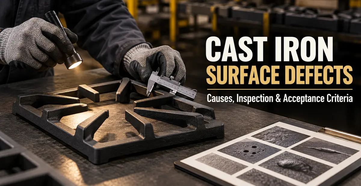
This guide explains common surface defects in cast iron components, their possible causes, a practical inspection method and the information appliance manufacturers and custom-component buyers should define before serial production.
What does cast iron surface quality actually mean?
An acceptable surface for a hidden industrial support is not necessarily acceptable for a visible gas-hob grate. On a consumer-facing part, uniform texture, safe edges, controlled flash and suitability for enamel or another coating carry greater importance. In assembly areas, dimensions, flatness, foot position and contact points may matter more than a minor irregularity on a non-functional surface.
A useful quality review should therefore answer at least three questions:
- Does the component conform to the drawing and agreed dimensional checks?
- Could the indication affect function, safety, assembly or coating durability?
- Does the appearance remain within the approved reference sample and buyer’s acceptance criteria?
For custom projects, these answers should be agreed before volume production. Alpha Plus describes its overall inspection route on the quality control page.
Common surface defects in cast iron components
1. Gas porosity and surface blowholes
These indications often appear as rounded holes or comparatively smooth cavities at or near the surface. Mould moisture, restricted gas escape, turbulent metal flow, core condition or dissolved gases may contribute. Appearance alone is rarely enough to identify the root cause; location, frequency, cavity shape and recurrence across parts should also be reviewed.
2. Shrinkage cavities and shrinkage porosity
Metal contracts as it solidifies. If a region is not fed adequately, a cavity or porous shrinkage structure can form. The risk is often associated with heavy sections, abrupt changes in thickness and local hot spots. Corrective action may involve feeding and gating, part geometry or pouring conditions rather than surface finishing alone.
3. Burnt-on sand, metal penetration and abnormal roughness
Strongly adhering sand, penetration of molten metal into the mould surface or unusually rough texture may relate to sand properties, mould coating, pouring temperature, mould compaction or metal pressure. Cleaning may improve appearance, but serial recurrence will continue unless the process cause is controlled.
4. Misrun and cold shut
In a misrun, metal stops before the mould cavity is filled and part of the component remains incomplete. A cold shut occurs when two metal fronts meet without joining correctly, leaving a line or seam. Metal temperature, flow rate, section thickness and gating design can all influence these defects.
5. Flash and parting-line mismatch
Flash forms where mould halves meet or around cores. Sharp flash can affect appearance, safe handling and assembly. Misalignment between mould halves can create a visible step and alter dimensions or seating surfaces. Mould condition, closure and the finishing operation require attention in these areas.
6. Hot tears and cold cracks
A crack is a critical indication and should be distinguished from a scratch or superficial line. Solidification stress, restricted contraction, unsuitable geometry, impact or thermal stress can contribute. Changes in section, sharp corners and load-bearing areas deserve especially careful inspection.
7. Distortion and loss of flatness
Uneven cooling, asymmetric design, early shakeout or unsuitable finishing conditions may distort a casting. On a gas-hob grate, distortion can cause rocking, poor foot contact or unstable cookware. Flatness should be checked from an agreed datum using a defined measuring method.
8. Enamel or coating defects
For enamelled cast iron, substrate quality and surface preparation directly affect the final coating. Bare spots, runs, blisters, hairline cracks, chips, colour variation and contamination can originate in preparation, application or firing. For more context on the coating, see what enamelled cast iron is.
Why one part rarely reveals the complete root cause
Different defects may look similar, and one defect may result from several interacting factors. A surface cavity, for example, could relate to gas, shrinkage, mould erosion or finishing. Root-cause analysis becomes more reliable when the following evidence is reviewed together:
- the defect’s position on the component and its relation to gates and feeders;
- recurrence within a particular cavity, shift, mould or melt;
- the shape of the indication at the surface and in section;
- records for raw material, sand, temperature and pouring time;
- dimensional results and any additional testing required;
- condition before and after blasting, grinding or coating.
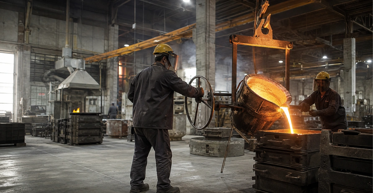
This is why inspection should be supported by records and traceability. The broader sequence is described in Alpha Plus’s guide to the cast iron production process.
How should cast iron parts be visually inspected?
Standardise viewing conditions
Lighting, viewing angle, distance and surface cleanliness should be kept as consistent as practical. An oily part under weak light cannot be compared fairly with a clean part under direct light. Visible components should be checked against an approved reference sample whenever possible.
Classify surfaces by importance
Not every area has the same purpose. Surfaces may be divided into primary cosmetic areas, contact surfaces, assembly zones and concealed non-functional areas. Permitted defect type, size and frequency can then be defined separately for each zone.
Connect visual and dimensional inspection
A visually attractive part can still be out of tolerance at a foot, height, flatness or functional spacing. Conversely, a small irregularity in a concealed area may remain acceptable under the agreed standard. The drawing, critical checkpoints and measuring method should govern the decision.
Record defects in measurable terms
Statements such as “the surface is bad” do not support corrective action. Record the indication type, position, approximate size, frequency, mould or batch number and a scaled photograph. This makes it possible to separate an isolated event from a repeating trend.
Define acceptance criteria before serial production
The right time to agree surface quality is not after thousands of components have been produced. Prototype or initial approval should establish:
- the technical drawing and its current revision;
- critical dimensions, tolerances and measuring points;
- classification of cosmetic and functional surfaces;
- permitted type, size and number of indications in each zone;
- an approved master sample or reference images;
- requirements for finishing, blasting, enamel or other coating;
- production sampling and batch-acceptance rules;
- handling of repairable, reworked and rejected parts.
When a component is made from a drawing or physical sample, the manufacturer’s production capabilities and process limits should be reviewed during the technical enquiry.
Buyer checklist for visible cast iron components
- Describe the component’s function and how the user or finished product interacts with it.
- Reconcile the 3D file, 2D drawing and physical sample where all are available.
- Separate genuinely critical tolerances from general dimensions.
- Mark important cosmetic surfaces on the drawing or an annotated image.
- Define coating colour, texture and gloss with a physical reference.
- Specify the stability, assembly and foot-contact checks.
- Define packaging that protects finished surfaces in transit.
- Approve initial samples and measurement results before serial ordering.
Defect prevention from design to packaging
Final inspection does not create quality; it only reveals the condition already produced. Reducing surface defects depends on continuity throughout the chain: suitable wall thickness and radii, sound methoding, controlled charge and sand, stable melting and pouring, appropriate shakeout timing, controlled finishing, surface preparation and protective packaging. Inspection feedback must return to the stage where the defect originated.
On a gas-hob grate, seating stability, alignment with burners, contact-point quality and coating consistency all matter at the same time. Reviewing Alpha Plus product models can help establish the required form before a technical enquiry.
Frequently asked questions
Does every small cavity reject a cast iron part?
No. The decision depends on its location, size, frequency, depth, component function and the agreed acceptance criteria. The same indication is evaluated differently on a visible or loaded surface than in a concealed, non-functional area.
Can grinding repair every surface defect?
Grinding can remove flash or correct limited areas, but it cannot solve internal porosity, cracking, incomplete filling or dimensional error. It can also alter geometry and texture. Rework therefore needs a defined method and limit.
Why can a defect become more visible after enamelling?
A coating may emphasise substrate roughness or contamination, and the application or firing process can introduce defects of its own. Raw casting quality and surface preparation should therefore be controlled before coating.
What is the value of a master sample?
A master sample creates a shared reference for colour, texture, finish and the acceptable level of certain cosmetic variations. It should be approved, dated and stored so it remains usable throughout production.
What information is needed for a manufacturing quotation?
Provide a drawing or sample, critical dimensions, material and target weight, coating, cosmetic criteria, order volume, packaging and delivery requirements. A complete technical enquiry supports a more accurate manufacturability and quality review.
Repeatable quality begins with clear criteria
The purpose of quality control is not merely to find a defective component. It should distinguish critical defects, acceptable cosmetic variation and normal process variation through measurable criteria. When the drawing, master sample, checkpoints and acceptance method are defined at the beginning, communication becomes clearer and serial production easier to control.
To discuss a standard component or a custom project, send drawings, photographs and the required volume through the Alpha Plus contact and cooperation page.